Appearance
Hot Well Module
Module Overview
The Hot Well module in Encast provides comprehensive modelling capabilities for thermal storage systems utilising hot water tanks, buffer vessels, and thermal storage containers. This module enables accurate simulation of thermal energy storage across diverse applications from residential hot water cylinders to large-scale industrial process heat storage systems.
Hot wells represent critical infrastructure for managing thermal energy supply and demand mismatches in heating systems, industrial processes, and district energy networks. The module accounts for various thermal storage configurations, heat exchange systems, and thermal loss characteristics to provide accurate performance predictions and energy storage capacity analysis throughout the system's operational life.
Unlike electrical energy storage systems, thermal storage operates with different physics governing heat transfer, thermal stratification, and temperature-dependent performance characteristics. The diversity of applications, from simple domestic hot water cylinders to sophisticated industrial thermal storage vessels, makes this module essential for comprehensive energy system analysis where thermal energy management is critical to overall system performance and economics.
Data Entry
Installation

Hot wells are added by selecting "Create new installation".
Installation Details

Name: Identifier for the installation.
Installation Design Life

Defines the operational period of the Hot Well.
- Installation Date: Date installation is complete.
- Decommission date (Optional): Date after which the installation is unavailable.
- Design Life (Optional): Number of years from installation date the installation will be available.
An installation date is required. If neither decommission date nor design life are present, the hot well is considered installed until the end of the simulation.
Hot Well Performance Details
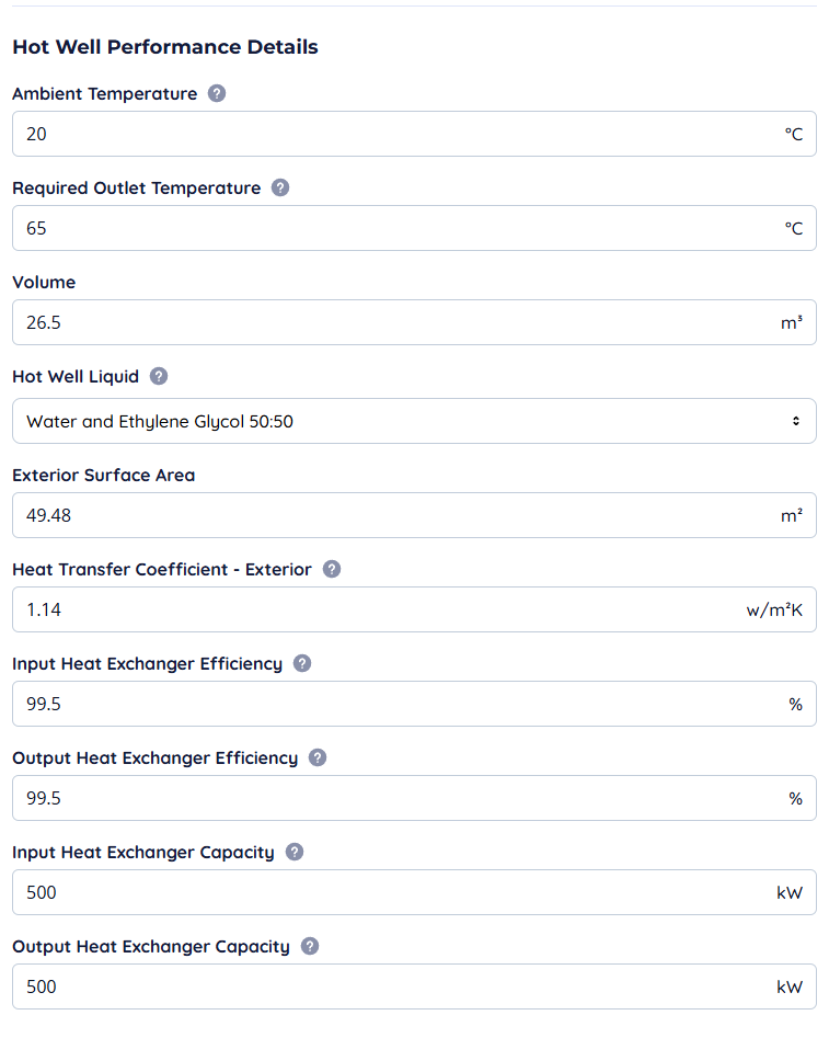
- Ambient Temperature: Annualised average temperature of environment.
- Required Outlet Temperature: Lowest usable output temperature.
- Volume: Fluid volume of the container.
- Hot Well Liquid: Type of liquid (e.g. Water, Glycol, or other fluids often used in cooling).
- Exterior Surface Area: Surface area of the container.
- Heat transfer Coefficient—Exterior: Total heat transfer coefficient from liquid to surrounding gas.
- Input Heat Exchanger Efficiency: Upstream efficiency of the heat exchanger in the system.
- Output Heat Exchanger Efficiency: Downstream efficiency of the heat exchanger.
- Input Heat Exchanger Capacity: Nominal input capacity in kWh of the heat exchanger.
- Output Heat Exchanger Capacity: Nominal output capacity in kWh of the heat exchanger.
Calculating Heat Transfer
This requires some thermodynamics to calculate if you do not have the information to hand, here is the methodology:
![]()
The above diagram shows the Hot Well system and how each required piece of information is used. The Heat Loss / 30 minutes on the left of the diagram is defined by the heat of the hot well, its surface area, and the ambient temperature.
Volume and Surface Area are relatively easy to do with a tape measure and calculation, for example, if you're doing this for a Cylinder, the Volume and Area are:
Heat Transfer Coefficient is defined by the characteristics of how heat can be transferred through a substance. In the example above, we have a Steel container with insulation applied to the outside.
The easiest method is to use Engineering Toolbox to find the Overall heat transfer coefficient. At the bottom of the page is the Multi-Layered Walls section:
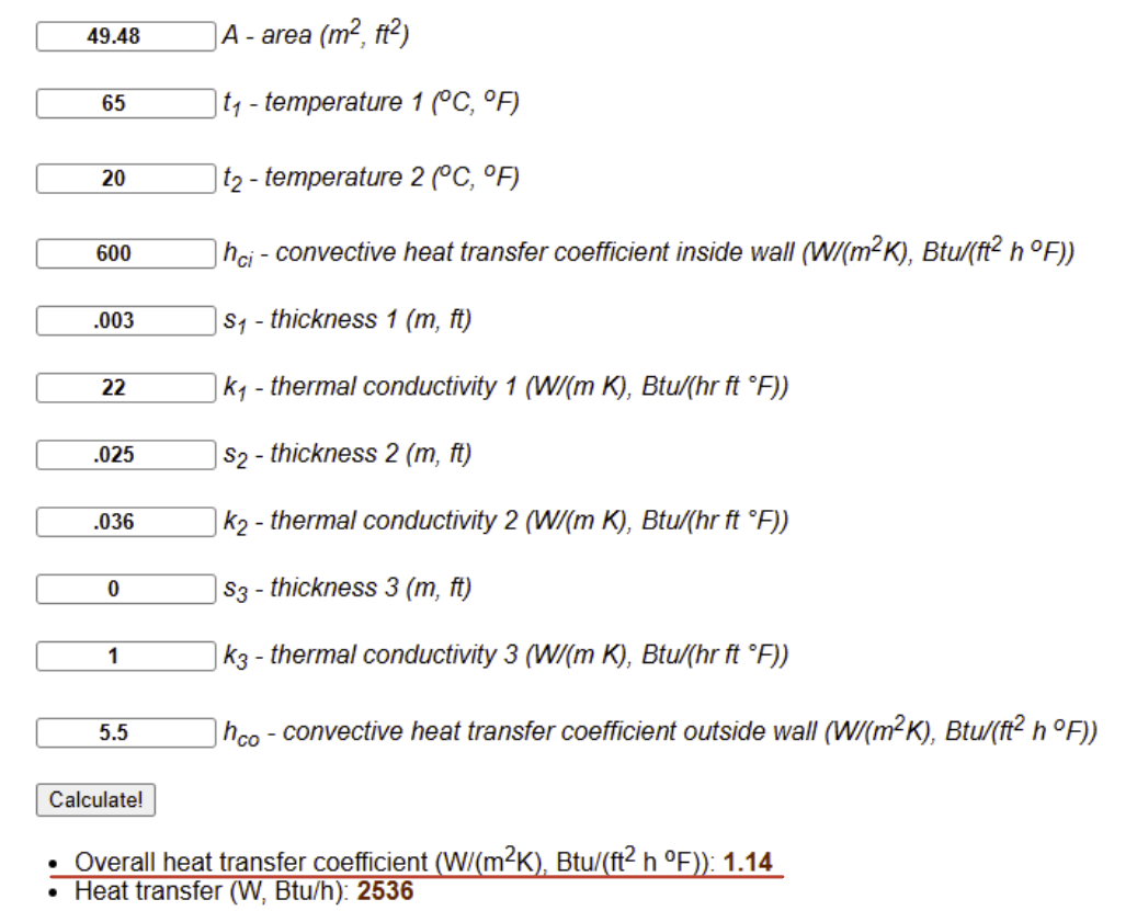
You can fill in the Area and temperatures. However, we don't need these for our purposes. We need to fill in the convective heat transfer coefficient, thickness of the walls, and their thermal conductivity.
In this example:
- hci - **Convection inside container——**The rate of energy transfer from the liquid (Water) to the tank (Steel)—600 W/m²K for free convection of water
- **s1——**Thickness of the tank (Steel)—3mm
- k1 - The rate of energy transfer through tank material (Steel) - 22 W/m²K
- **s2——**Thickness of the Insulation (glass mineral wool)—25mm
- **k2——**The rate of energy transfer through the insulation material (glass mineral wool)—0.036 W/m²K
- hco - **Convection outside container——**The rate of energy transfer from the air to the insulation (glass mineral wool)—5 W/m²K for a hot surface in air.
Values for h can be challenging to assign, here are some general and useful values to use:
| Flow types | Values of h (W/m²K) |
|---|---|
| Forced convection; low speed flow of air over a surface | 10 |
| Forced convection; moderate speed flow of air over a surface | 100 |
| Forced convection; moderate speed cross-flow of air over a cylinder | 200 |
| Forced convection; moderate flow of water in a pipe | 3000 |
| Forced convection; molten metals | 2,000-45,000 |
| Forced convection; boiling water in a pipe | 50,000 |
| Forced Convection - water and liquids | 50-10,000 |
| Free Convection - gases and dry vapors | 5-37 |
| Free Convection - water and liquids | 50-3000 |
| Vertical plate in air with 30°C temperature difference | 5 |
| Boiling Water | 3,000-100,000 |
| Water flowing in tubes | 5-100 |
| Condensing Water Vapor | 5-100 |
| Water in free convection | 100-1200 |
| Oil in free convection | 50-350 |
| Gas flow on tubes/between tubes | 10-350 |
Operational Times and Maintenance

- Operational Times can be used to define the times when an installation is active.
- Maintenance is used to create shutdown periods to maintain assets or automatic costs based on the amount of hours an installation has run.
These are explained in more detail in the Operational Times and Maintenance Section after Modules.
Specialisations and Use Cases
Integration with Other Systems
Hot wells complement renewable energy systems and thermal generation technologies by:
- Providing thermal energy storage to smooth supply and demand mismatches in heating systems
- Supporting renewable heat integration through storing excess thermal energy during peak production periods
- Enabling district heating systems with thermal storage for peak demand management and system stability
- Facilitating combined heat and power systems by storing waste heat for later utilisation
Residential and Commercial Applications
Hot wells serve critical roles across diverse residential and commercial thermal applications, each requiring specific sizing and performance characteristics based on heating demand patterns and system integration requirements. Residential installations typically utilise domestic hot water cylinders ranging from 150-500 litres capacity, providing stored hot water for bathing, washing, and space heating applications in combi-boiler systems.
Commercial buildings leverage larger thermal storage systems for space heating applications, domestic hot water supply, and process heating requirements. Office buildings and hotels often incorporate buffer vessels ranging from 1,000–10,000 litres to provide thermal stability for heat pump systems and reduce cycling losses in heating equipment. These installations frequently integrate with building management systems to optimise charging schedules based on occupancy patterns and electricity tariff structures.
Healthcare facilities represent demanding applications where hot wells provide critical thermal storage for domestic hot water systems with strict temperature maintenance requirements and anti-Legionella protocols. These systems often incorporate multiple temperature zones with sophisticated circulation and monitoring systems to ensure continuous availability while meeting regulatory compliance requirements.
Educational institutions and public buildings utilise thermal storage systems for district heating applications, where centralised hot wells provide thermal buffering for multiple buildings served by common heating plants. These installations often incorporate sophisticated control systems that optimise thermal storage charging based on occupancy schedules, weather forecasts, and energy pricing structures.
Industrial Process Applications
Industrial facilities utilise hot wells for diverse process heating applications requiring thermal energy storage at specific temperature ranges and capacities. Manufacturing operations leverage thermal storage for process heating applications where production schedules create intermittent heat demand patterns, enabling more efficient operation of central heating systems through load levelling and peak demand reduction.
Food processing facilities incorporate hot wells for process heating, cleaning operations, and sterilisation applications where consistent thermal energy availability is critical for production continuity and food safety requirements. These systems often integrate with heat recovery systems to capture waste heat from cooking and processing operations, storing recovered energy for subsequent use in cleaning and sanitisation processes.
Chemical processing and pharmaceutical manufacturing utilise thermal storage for precise temperature control in reaction vessels, distillation processes, and equipment heating applications. The thermal mass provided by hot wells enables stable process temperatures while reducing the cycling frequency of heating equipment, improving both process quality and equipment longevity.
Textile and paper manufacturing industries leverage thermal storage systems for process heating applications requiring large quantities of hot water or steam. These installations often incorporate sophisticated heat recovery systems that capture waste heat from drying operations and high-temperature processes, storing recovered energy for subsequent use in lower-temperature applications.
Specialised Configurations
- Stratified Storage Systems: Multiple temperature zones within single vessels for optimised thermal storage
- Phase Change Material Integration: Enhanced thermal storage capacity through latent heat storage systems
- District Heating Storage: Large-scale thermal storage for community heating networks
- Industrial Process Integration: Specialised thermal storage for specific industrial process requirements
Sensitive Parameters
Hot well performance and system integration depend critically on several key parameters that must be carefully considered during design and throughout the operational life. Thermal stratification characteristics fundamentally determine the effective storage capacity and thermal efficiency of the system, with poor stratification leading to reduced usable thermal storage and increased mixing losses. The relationship between inlet and outlet arrangements, flow rates, and temperature differences directly affects the degree of thermal stratification achievable within the storage vessel.
Heat loss characteristics represent another critical parameter, with thermal insulation quality and ambient temperature conditions significantly affecting the thermal retention performance of the system. The heat transfer coefficient through the vessel walls and insulation system determines the rate of thermal energy loss, directly impacting the overall system efficiency and the frequency of reheating cycles required to maintain usable temperatures.
Heat exchanger sizing and efficiency parameters critically affect both the charging and discharging rates of the thermal storage system. Undersized heat exchangers limit the rate at which thermal energy can be stored or extracted, potentially creating bottlenecks in system performance during peak demand periods. The thermal mass of the storage medium and the specific heat capacity of the storage fluid determine the overall thermal storage capacity and temperature rise characteristics of the system.
Control system integration and temperature management strategies significantly influence operational efficiency and thermal storage utilisation. Poor control algorithms can lead to excessive cycling, thermal mixing, and reduced storage efficiency, while sophisticated control systems can optimise charging schedules, minimise thermal losses, and maximise the utilisation of stored thermal energy.
Economic Sensitivities
- Insulation Quality: Poor thermal insulation leads to higher heat losses and increased energy consumption
- Heat Exchanger Sizing: Undersized heat exchangers limit charging and discharging rates, affecting system performance
- Storage Fluid Selection: Different thermal storage media affect both capacity and system costs
- Control System Sophistication: Advanced control systems improve efficiency but increase capital costs
Technical Risk Factors
- Thermal Stratification Management: Poor stratification reduces effective storage capacity and system efficiency
- Corrosion and Scale Formation: Water quality affects long-term system integrity and heat transfer performance
- Temperature Control Accuracy: Process applications requiring precise temperatures need sophisticated control systems
- Thermal Cycling Effects: Repeated heating and cooling cycles affect vessel integrity and insulation performance
Regulatory and Environmental Considerations
- Legionella Risk Management: Hot water storage systems require specific temperature maintenance and monitoring protocols
- Pressure Vessel Regulations: Thermal storage systems may require pressure vessel certification and inspection
- Building Standards: Installation requirements for thermal storage systems in commercial and residential buildings
- Energy Efficiency Standards: Thermal storage system efficiency requirements and performance disclosure standards
- Water Quality Requirements: Regulatory standards for domestic hot water systems and process applications